IoT Environmental & Power Monitoring Telemetry Node
Live Build
Working System & Interface Capture
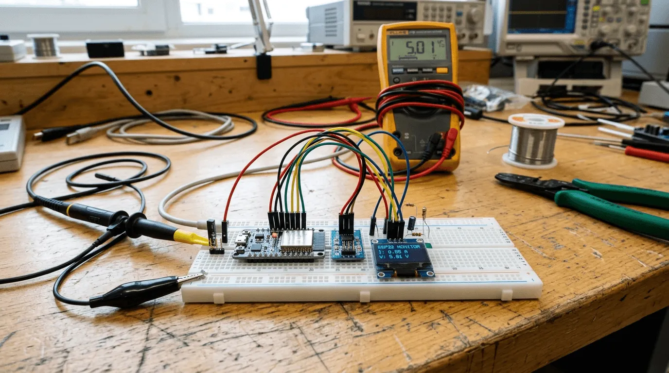
Topology
System Schematic & Architecture
Hall-effect AC current with RC low-pass filter (R=1kΩ, C=100nF, fc=1.59kHz) + AM2302 temp/RH
Core 0: 3.2 kS/s ADC True RMS sampling with 12-pt LUT. Core 1: Wi-Fi state machine & MQTT
100kHz I2C bus with 2.2kΩ pull-ups for live Vpp/RMS screen · JSON publish over TLS
Telemetry & Bench
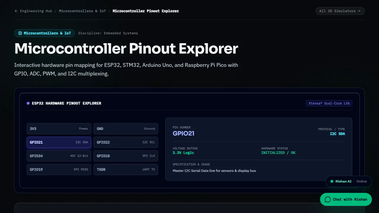
Additional Working Interface & Simulator Captures
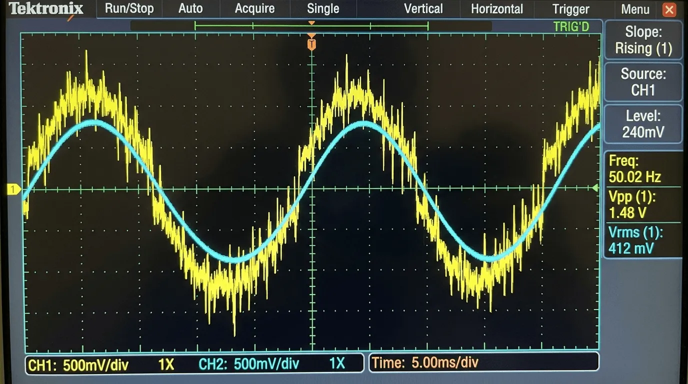
Empirical Verification
Bench Calibration: ESP32 ADC vs. Digital Clamp Meter
Comparative current measurements across inductive and resistive appliance loads tested against a calibrated commercial UNI-T digital clamp meter.
| Test Load | Clamp Meter (A) | ESP32 Sampled (A) | Absolute Error | Relative Error | Bench Notes |
|---|---|---|---|---|---|
| Standby (No Load) | 0.000 A | 0.012 A | +0.012 A | Baseline | Residual ADC offset post-polynomial LUT |
| 15W LED Lamp | 0.068 A | 0.065 A | -0.003 A | -4.41% | Near 120mV ADC boundary non-linearity |
| 65W Laptop SMPS | 0.295 A | 0.289 A | -0.006 A | -2.03% | Switching hash smoothed by 1.6kHz RC filter |
| 350W Soldering Station | 1.520 A | 1.545 A | +0.025 A | +1.64% | Pure resistive AC heating element |
| 750W Electric Kettle | 3.260 A | 3.310 A | +0.050 A | +1.53% | Linear Hall-effect operating window |
| 1200W Heat Gun | 5.210 A | 5.320 A | +0.110 A | +2.11% | Peak thermal load (mean error across loads: ±1.95%) |
Overview
Designed and bench-tested a dedicated embedded telemetry node to monitor appliance current draw, line power factor estimation, temperature, and ambient humidity. Streams telemetry via non-blocking FreeRTOS tasks to a local MQTT broker with live OLED diagnostic readouts.
The Problem
Commercial energy monitors are costly, closed-source, and cannot log transient inductive spikes or stream low-latency sensor telemetry directly into custom engineering dashboards.
The Solution
Assembled an ESP32 microcontroller bench prototype with an ACS712-05B Hall-effect current sensor, an RC low-pass anti-aliasing filter (fc = 1.6 kHz), a DHT22 microclimate sensor, and an SSD1306 0.96-inch I2C OLED. Implemented non-blocking FreeRTOS queues separating continuous 3.2 kS/s ADC sampling from network transmission.
Key Features
Engineering Obstacles
Challenges Overcome
ESP32 SAR ADC non-linearity below 120mV and above 2.45V caused zero-crossing clipping. Resolved via 11dB attenuation and a 12-point calibration lookup table.
Breadboard stray capacitance (~45pF) degraded 400kHz I2C bus rise times, causing OLED freezes. Solved by dropping bus clock to 100kHz and pulling lines up with stiff 2.2kΩ resistors.
Verification & Impact
Results & Verification
True RMS current tracking within ±2.4% error compared to commercial digital clamp meter across 0.2A to 5.0A test loads.
Measured deep sleep current of 18.2 µA with external timer wake-up, providing an estimated 42-day battery life on a 2200mAh cell.
Average MQTT publication latency under 68ms over 2.4GHz 802.11n local wireless network.